The Tow In: What the Customer Said and What the Key Cycle Showed
The car rolled off the flatbed just after 9 AM, a late-model sedan that had died in traffic and would crank but not start. The driver was a regular customer. Her first words matched the note on the work order: "It just quit. It cranks, but nothing happens." That single line was all the information the office had at drop-off. There was no dashboard warning light reported, no odd noises, and no history of hard starts or recent repairs. The first step was clear: verify the complaint and document what happened with the key in hand.
After checking the paperwork, the technician cycled the key. The dash lights swept. The starter engaged. The engine spun over at normal RPM, but there was no hint of catching. No misfire, no stumble, just crank. The next step: confirm the basics. This is where the clock begins for any diagnostic charge. In many shops, the first hour is a flat diagnostic rate, not a promise to solve the problem but enough time to cover the essentials and, if possible, point the way forward with evidence.
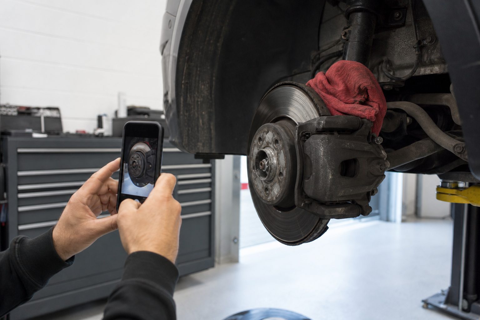
Keep reading: How to Shoot Brake, Tire, and Fluid Photos a Customer Can Read
Hour One: Verify the Complaint, Check Fuel, Spark and Compression
The technician started by verifying the no-start condition. He pulled the service history and checked for repeat complaints. No patterns jumped out. Next, he confirmed battery voltage was healthy, above 12 volts at rest. With a jumper pack on standby, he moved to the three essentials: fuel, spark, and compression. These steps are routine, but each takes time to prove.
Fuel: Pressure and Injector Pulse
A fuel pressure gauge on the rail showed pressure built as expected during cranking. No drop-off. The technician hooked up a noid light to an injector connector. The light flashed with each crank, confirming that the PCM was commanding fuel. He removed the fuel cap and sniffed for raw gas. None. He cracked a line at the rail, no air, just a faint mist. Fuel supply was present, and injector pulse was there.
Spark: Quick Checks and Coil Test
Popping a coil and plugging in a spark tester, he cranked the engine and saw a strong blue spark jump the gap. No fouling on the plug. He checked a second cylinder to be sure. Both showed spark, eliminating a total ignition failure. The shop kept a known-good plug in the drawer for quick swaps. This step ruled out a dead coil pack, at least for these cylinders.
Compression: The Handheld Gauge
Finally, he threaded in the compression tester. The first cylinder read at spec. He moved to the next, then a third. All showed healthy numbers. No broken timing belt, no obvious valve issue. These basics took about 30 minutes, including setup and teardown. With the essentials covered and no quick fix in sight, the next move was interrogating the car's memory for clues.
Reading Freeze Frame and Live Data Before Touching a Wire
Modern no-starts often leave a trail in the scan tool. Before chasing wires, the technician connected the scanner. The PCM showed no current codes, but a freeze frame from the last event held some clues. The RPM signal was present during crank, meaning the crankshaft position sensor was working. No obvious security or immobilizer code. Coolant and air temperature readings were plausible for a cold start. Battery voltage stayed steady.
He moved to live data. The throttle position sensor tracked with pedal movement. The mass air flow sensor showed some flow during crank. Manifold absolute pressure was near atmospheric, as expected. The technician noted fuel trims and O2 sensor readings, but with a no-start, these values remained static. Still, nothing out of range. He checked the immobilizer status, no lockout. The scan tool also showed the PCM was commanding injector pulse and spark, matching what he had seen with physical tests.
Ten more minutes went into double-checking these numbers and recording the readings for the service advisor. With no obvious code and no security issue, the problem was likely somewhere in the wiring, connectors, or a mechanical failure that sensors did not catch. The first hour closed with a list of test results, all showing "normal" but with the car still dead on the floor.
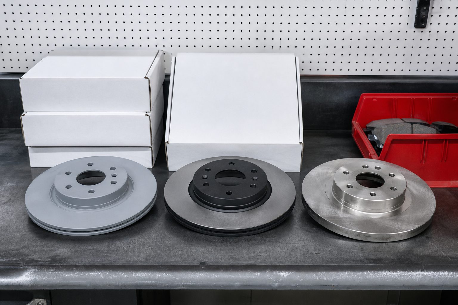
Keep reading: OE, Aftermarket, and Remanufactured Parts: Cost, Warranty, and Fit
Hour Two: Wiring Diagram, Voltage Drop and the Ground Side
With basics verified, the diagnostic process shifted from global checks to focused circuit tracing. The technician pulled factory wiring diagrams for the fuel and ignition systems. He traced the power and ground supply to each key component, starting with the fuel injectors and ignition coils. In many no-starts, voltage drop or a broken ground is the hidden culprit, especially in older vehicles or those with recent collision repair.
Power Feed Checks
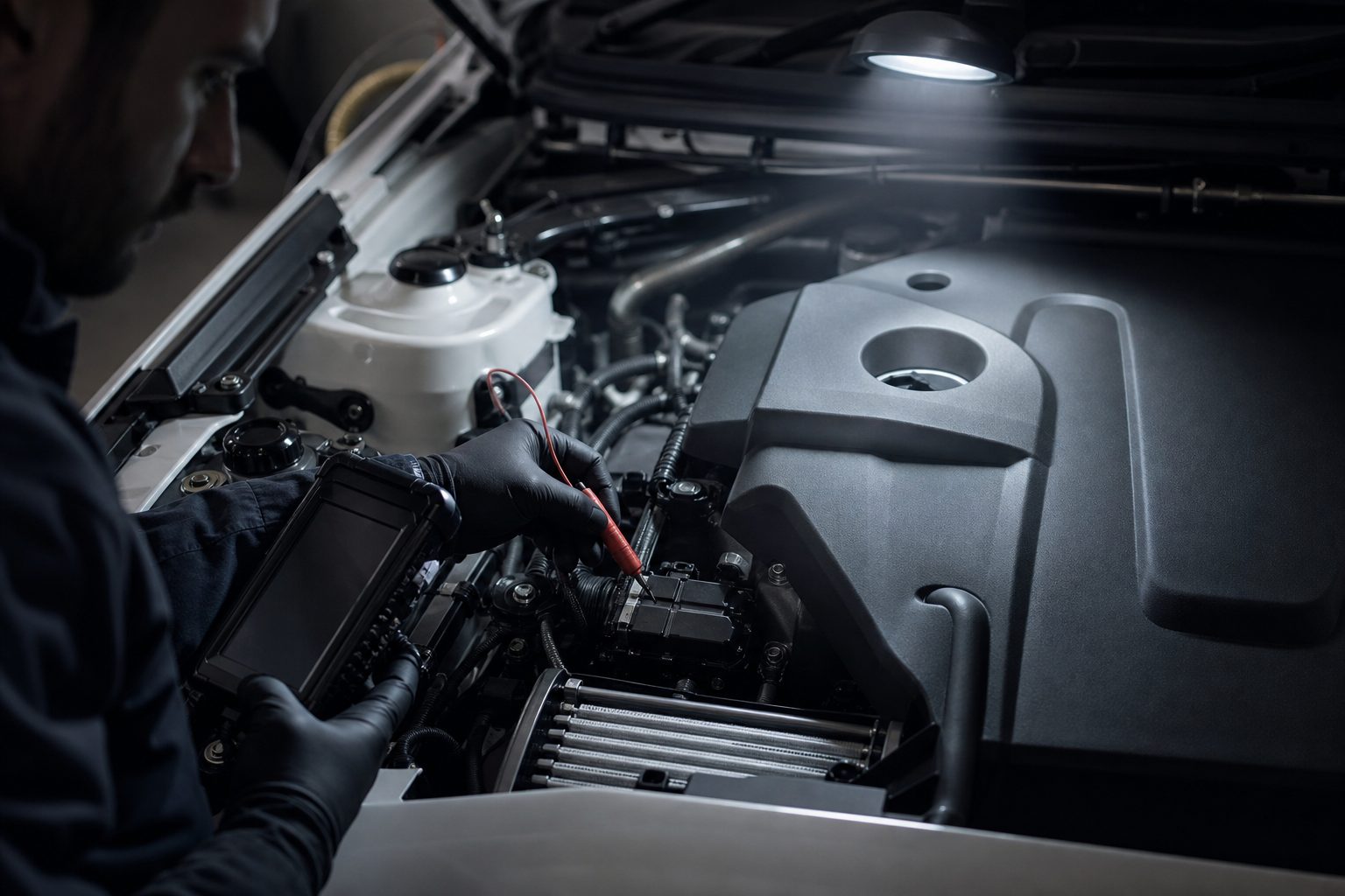
Using a backprobe, he measured voltage at the injector and coil connectors with the key on, then during crank. Both showed battery voltage. He loaded the circuit with a test light as a secondary check. The light glowed bright, confirming solid power feed under load.
Ground Side: Drop Testing
Next, he moved to the ground side. Backprobing the ground wire, he measured resistance between the connector pin and battery negative. The reading was low, no open ground. But when he performed a voltage drop test during cranking, he saw nearly one volt of drop on the ground side of the injectors. On a healthy circuit, this number typically stays well below half a volt. One volt meant resistance was hiding somewhere between the connector and chassis ground. This test, which takes a few minutes per circuit, pointed to a likely cause of weak or no injector operation, despite the PCM command and good power feed.
The technician checked the integrity of the ground at the engine block. He tugged the main ground strap and found it intact. But on closer inspection, the auxiliary ground wire near the harness junction showed some green corrosion around the eyelet. He disassembled the connector, finding it tight but corroded enough to cause resistance under load. A quick cleaning and retest dropped the voltage loss to nearly zero, but the engine still would not fire.
With nearly two hours in, the technician had identified a likely contributor but not the root cause. He went back to the diagrams and began checking continuity through the PCM driver circuits. By now, the labor clock was ticking toward a second hour, which in most shops means a new line item on the estimate and a call to the customer with a progress report.
The Component That Tested Fine and the Connector That Did Not
Many shops have seen components test fine in theory but fail due to wiring or connector issues. In this case, the next suspect was the crankshaft position sensor, even though scan data showed RPM during crank. The technician backprobed the sensor signal at the PCM and saw a good waveform on the scope. He checked the corresponding connector at the sensor itself, a common failure point on this model, where heat and oil degrade the plastic and pins.
The connector looked clean, but when he wiggled the harness, the car stumbled for a split second as if trying to catch. A second technician watched the scan tool and called out a momentary drop in RPM signal. The tech unplugged the connector, spread the pins slightly, and reconnected. This time, the engine fired briefly, then died again. The culprit was not the sensor itself but a loose tension fit in the connector pins, causing intermittent contact that fooled the PCM and all previous tests.
This is where diagnostic time pays off. Physical inspection combined with live monitoring can catch failures that no code or static test will reveal. Many shops have found that connectors, especially those exposed to engine heat and vibration, can pass voltage and resistance tests but fail under real-world conditions. Fixing this required careful cleaning and slightly adjusting the pin grip, not replacing the sensor or PCM.
See how InspectBay handles this for automotive repair
Hour Three: Repair, Retest and the Drive Cycle That Confirms It
With the connector repaired, the technician cleared the PCM memory and cranked the engine again. This time, it fired and ran. He let it idle and watched scan data for several minutes. No codes returned. The customer's complaint was gone, but the job was not done. The next step was a real-world drive cycle to ensure the fix held under load.
Retest Under Load
The technician took the car out for a short drive, monitoring live data. He watched for any dropout in RPM, injector pulse, or voltage during acceleration and deceleration. The car performed normally. He checked for pending codes and confirmed monitors completed without error. He pulled over and cycled the key several times, making sure the problem did not recur with temperature changes or vibration. Many intermittent electrical faults return after a heat soak, so this step is critical for confidence in the repair.
Back at the shop, he performed a final visual check of the repaired connector and ground. Everything held. The technician reinstalled covers and cleaned up tools. The last step before returning the car was documenting the work and preparing the story for the service advisor.
Writing the Diagnostic Story So the Time Bills Without a Fight
Many shop owners know that billing for diagnostic time can be contentious, especially when the repair is simple but the diagnosis is not. The key is clear, detailed documentation. This starts with the work order, which should show the verified complaint, the steps taken, and the evidence for each test. The technician's notes must describe not just what was found but what was ruled out, such as confirming good fuel and spark, showing scan data with no codes, and detailing voltage drop findings.
Photographs help. A shot of the corroded ground connector or the loose harness pin shows the customer and the advisor that the problem was real, not guessed. Many shops attach these images to the digital vehicle inspection report. Severity grading can clarify which findings were critical and which were preventive. When the customer sees that hours were spent chasing intermittent signals, rather than swapping parts, the bill makes sense. "Found intermittent no start caused by poor tension in crank sensor connector; verified all basics, voltage drop tested, confirmed with scope" is stronger than "repaired wiring."
Finally, the advisor should be prepared to explain that diagnostic time covers the process, not just the part. This protects the shop's labor margin and builds trust with customers, especially when the fix itself is minor but the path to finding it was not.
Tools that combine technician photos, severity grading, and one-link customer approval make this process smoother. They allow the shop to show exactly where the time went and why the diagnostic charge was justified, without chasing down paperwork or hoping the customer remembers a phone call.